Table of Contents Show
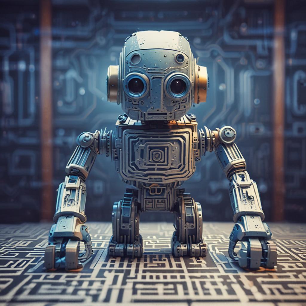
Ever dreamed of building a robot that can navigate complex mazes? This guide will show you how! Combining robotics, programming, and problem-solving, a maze solver robot is not only a fun weekend project but also a fantastic way to dive deep into the world of Arduino and autonomous systems. Whether you’re a beginner or an intermediate hobbyist, this step-by-step tutorial will walk you through every stage — from assembling the hardware to uploading the code that brings your robot to life. By the end, you’ll have a fully functional robot capable of exploring mazes using smart decision-making logic.
Step-by-Step Process
Gather Components
Collect Arduino board, motors, sensors, chassis, and power supply.
Assemble the Robot
Mount motors, sensors, and Arduino on the chassis, connect wiring.
Write the Code
Develop Arduino sketch for sensor input and motor control algorithms.
Test the Robot
Run initial tests to ensure sensors and motors function correctly.
Implement Maze Logic
Program the robot to navigate the maze using sensor data.
Process infographic for Build a Maze Solver Robot Using Arduino – Step-by-step Guide
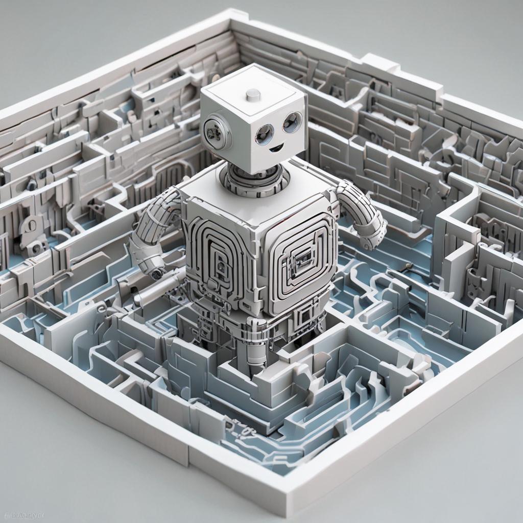
Understanding the Maze Solver Robot
A maze solver robot is an autonomous machine designed to navigate through a maze from a starting point to an exit. It uses sensors to detect walls and pathways, then applies algorithms to determine the best route. These robots are commonly used in robotics competitions and serve as excellent learning tools for understanding sensors, motor control, and algorithmic thinking.
There are several maze-solving algorithms, each with its own strengths. The wall follower algorithm, also known as the right-hand or left-hand rule, is one of the simplest and most reliable for mazes with continuous walls. It works by keeping one side of the robot in constant contact with a wall, effectively tracing the perimeter until the exit is found. While it doesn’t always find the shortest path, it guarantees a solution in simply connected mazes.
This guide will focus on implementing the wall follower algorithm using infrared (IR) sensors and an Arduino Uno. It’s beginner-friendly and provides a solid foundation for exploring more advanced techniques later.
Gathering Your Components: The Essential Parts List
Before you begin building, make sure you have all the necessary components. Most of these are readily available online and can be purchased individually or as part of a robotics kit. Below is a detailed list with estimated costs and suggested Amazon links for convenience.
Complete Components List
- Arduino Uno R3 – $20–25 – The brain of the robot. It reads sensor data and controls motor movement. Buy on Amazon
- Motor Driver Module (L298N) – $3–5 – Controls the direction and speed of the DC motors. Buy on Amazon
- DC Motors with Encoders (2x) – $12–15 – Geared motors with built-in encoders for better speed control and feedback. Buy on Amazon
- Robot Chassis (with wheels) – $10–15 – A two-wheeled or four-wheeled platform to mount all components. Buy on Amazon
- Infrared (IR) Sensors (5x) – $10–12 – Used to detect walls. We recommend 5 sensors: one front, two sides, and two diagonals. Buy on Amazon
- Battery Pack (6V or 7.4V) – $8–10 – Powers the motors and Arduino (via Vin or external power). Use AA batteries or a LiPo pack. Buy on Amazon
- 9V Battery and Connector (optional) – $5 – Alternative power source for Arduino. Use voltage regulator if needed.
- Breadboard (mini) – $3 – Useful for prototyping sensor connections.
- Jumper Wires (male-to-male and male-to-female) – $5 – For connecting components.
- USB Cable (Type A to B) – $3 – For uploading code to the Arduino.
- Screws, Nuts, and Double-Sided Tape – $5 – For securing components.
- Soldering Iron and Solder (optional) – $15–20 – For permanent wiring (not required for breadboard setup).
Total Estimated Cost: $90–120, depending on component quality and whether you already own some parts. Consider purchasing a robotics starter kit to save money and time.
Assembling the Robot: A Step-by-Step Guide
With all components ready, it’s time to build your robot. Follow these steps carefully and refer to diagrams or images where possible for clarity.
Chassis Assembly
Begin by assembling the robot chassis according to the manufacturer’s instructions. Most kits snap together or require simple screwing. Ensure the structure is sturdy and balanced. If using a custom or 3D-printed chassis, verify that all mounting holes align with the motors and electronics.
Mounting the Motors and Wheels
Attach the DC motors to the designated slots on the chassis using screws. Make sure they’re securely fastened and spin freely. Then, press the wheels onto the motor shafts. If your robot uses caster wheels in the front or back, install them now to ensure smooth movement.
Connecting the Motor Driver
Plug the motor wires into the L298N driver’s output terminals (OUT1, OUT2 for left motor; OUT3, OUT4 for right motor). The red wire typically goes to the positive terminal. Double-check polarity to prevent reverse rotation.
Installing the IR Sensors
Mount the five IR sensors on the front and sides of the robot using small brackets or double-sided tape. Position them so they can detect walls at a distance of 2–5 cm. A typical layout includes:
- One centered front sensor
- Left and right side sensors (90°)
- Left and right diagonal sensors (45°)
This configuration allows the robot to detect open paths and make informed turning decisions.
Wiring the Sensors and Motor Driver to the Arduino
Connect the L298N and IR sensors to the Arduino as follows:
- L298N IN1 → Arduino Pin 8
- L298N IN2 → Arduino Pin 9
- L298N IN3 → Arduino Pin 10
- L298N IN4 → Arduino Pin 11
- L298N ENA → Arduino Pin 5 (PWM for left motor speed)
- L298N ENB → Arduino Pin 6 (PWM for right motor speed)
- IR Sensor Front → Arduino A0
- IR Sensor Left → Arduino A1
- IR Sensor Right → Arduino A2
- IR Sensor Diagonal Left → Arduino A3
- IR Sensor Diagonal Right → Arduino A4
All sensors and the motor driver should share common GND and VCC connections to the Arduino or breadboard.
Connecting the Power Supply
Connect the battery pack to the L298N’s 12V input terminal. The L298N can power the Arduino via its 5V output pin (only if input voltage is ≤12V). Alternatively, power the Arduino separately using a 9V battery connected to the barrel jack. Always verify polarity before powering up to avoid damaging components.
Programming the Arduino: The Maze-Solving Algorithm
Now that the hardware is built, it’s time to bring your robot to life with code. We’ll use the Arduino IDE to program the wall-following logic.
Setting Up the Arduino IDE
Download and install the Arduino IDE from the official website. Connect your Arduino via USB, select the correct board (Arduino Uno) and port, and test the connection with the built-in Blink example.
Defining Pin Assignments
In your code, start by defining which pins are connected to motors and sensors. This makes the code easier to read and modify later.
Reading Sensor Values
The IR sensors output LOW when a wall is detected and HIGH when no wall is present. Use digitalRead() to check each sensor. Calibration may be needed based on ambient light and surface reflectivity.
Implementing the Wall-Following Algorithm
The robot will follow the right-hand wall using this logic:
- If a wall is detected on the right, move forward.
- If no wall is on the right but one is ahead, turn right.
- If no wall is on the right or ahead, turn right to find the wall.
- If a wall is ahead but no wall on the right, turn left to explore.
This ensures the robot sticks to the right wall and eventually finds the exit.
Motor Control Functions
Create functions like moveForward(), turnLeft(), turnRight(), and stop() to control motor direction using the L298N inputs and PWM pins for speed control.
Complete Arduino Code
// Maze Solver Robot - Wall Follower Algorithm
// Uses 5 IR sensors and L298N motor driver
// Motor pins const int IN1 = 8, IN2 = 9, IN3 = 10, IN4 = 11; const int ENA = 5, ENB = 6;
// Sensor pins const int frontSensor = A0; const int rightSensor = A2; const int leftSensor = A1; const int diagRight = A4; const int diagLeft = A3;
void setup() { pinMode(IN1, OUTPUT); pinMode(IN2, OUTPUT); pinMode(IN3, OUTPUT); pinMode(IN4, OUTPUT); pinMode(ENA, OUTPUT); pinMode(ENB, OUTPUT); }
void loop() { int front = digitalRead(frontSensor); int right = digitalRead(rightSensor); int left = digitalRead(leftSensor); int dRight = digitalRead(diagRight); int dLeft = digitalRead(diagLeft);
// Wall-following logic (right-hand rule) if (right == LOW) { moveForward(); } else if (front == LOW) { turnRight(); } else if (left == LOW) { turnLeft(); } else { turnAround(); } }
void moveForward() { digitalWrite(IN1, HIGH); digitalWrite(IN2, LOW); digitalWrite(IN3, HIGH); digitalWrite(IN4, LOW); analogWrite(ENA, 200); analogWrite(ENB, 200); }
void turnRight() { digitalWrite(IN1, HIGH); digitalWrite(IN2, LOW); digitalWrite(IN3, LOW); digitalWrite(IN4, HIGH); analogWrite(ENA, 200); analogWrite(ENB, 200); delay(400); // Adjust based on robot turning speed }
void turnLeft() { digitalWrite(IN1, LOW); digitalWrite(IN2, HIGH); digitalWrite(IN3, HIGH); digitalWrite(IN4, LOW); analogWrite(ENA, 200); analogWrite(ENB, 200); delay(400); }
void turnAround() { turnRight(); turnRight(); }
void stopRobot() {
  digitalWrite(IN1, LOW);
  digitalWrite(IN2, LOW);
  digitalWrite(IN3, LOW);
  digitalWrite(IN4, LOW);
}
Upload this code to your Arduino and test it on a simple maze drawn with black tape on a white surface.
Testing and Calibration
Testing is crucial to ensure your robot performs reliably in different environments.
Initial Testing
Before running the full maze algorithm, test each component:
- Upload a simple motor test sketch to verify both wheels move forward and backward.
- Use the Serial Monitor to print sensor values and confirm they detect walls correctly.
Sensor Calibration
IR sensors can be sensitive to light. Place the robot in your testing environment and use the Serial Monitor to observe sensor readings. Adjust the sensor sensitivity using the potentiometer on each module until they reliably detect walls at 2–3 cm distance.
Motor Calibration
If your robot veers to one side, adjust the PWM values for each motor in the moveForward() function. For example, if it turns left, increase the left motor speed slightly until movement is straight.
Troubleshooting
- Robot not moving: Check power connections, motor wiring, and ensure ENA/ENB pins are connected to PWM outputs.
- Erratic sensor readings: Shield sensors from ambient light or recalibrate them.
- Robot stuck in loops: Fine-tune turn delays or add logic to prevent oscillation.
Advanced Features (Optional)
Once your robot works reliably, consider enhancing it with advanced features.
Using Encoders for Precise Movement
If your motors have encoders, use interrupts to count pulses and measure distance traveled. This allows the robot to know exactly how far it has moved, improving navigation accuracy.
Implementing a More Advanced Maze-Solving Algorithm
Upgrade from wall follower to the flood-fill algorithm, which maps the entire maze and finds the shortest path. It requires memory to store maze data and more complex logic but offers optimal performance.
Adding an LCD Display
Connect a 16×2 LCD to show real-time sensor data, robot state, or maze progress. Use the LiquidCrystal library to display messages like “Turning Right” or “Wall Detected.”
Conclusion
Building a maze solver robot with Arduino is a rewarding project that blends electronics, mechanics, and programming into one exciting challenge. By following this guide, you’ve assembled a functional robot capable of autonomously navigating mazes using smart logic. You’ve learned how to wire sensors and motors, implement a wall-following algorithm, and troubleshoot common issues. But this is just the beginning — now you can experiment with better algorithms, add sensors, or even enter robotics competitions. The skills you’ve developed here are foundational for more advanced robotics projects. Share your creations and questions in the comments below — we’d love to see what you build!
FAQ (Frequently Asked Questions)
What if my robot is not moving straight?
This is usually due to unequal motor speeds. Calibrate by adjusting the PWM values in the analogWrite() commands for ENA and ENB until both motors spin at the same speed. Also, check wheel alignment and surface traction.
How can I improve the robot’s accuracy?
Use more sensors for better wall detection, implement encoder feedback for precise distance measurement, and fine-tune turning delays. Testing in consistent lighting also helps IR sensors perform reliably.
What are some alternative sensors I can use?
Ultrasonic sensors (like HC-SR04) can detect walls at longer ranges and are less affected by surface color. However, they are slower and may require additional filtering. For line-following mazes, use IR reflectance sensors instead.
Can I use a different Arduino board?
Yes! Boards like Arduino Nano, Mega, or ESP32 can work too. Just ensure they have enough digital I/O pins and PWM outputs for your sensors and motors. Adjust pin assignments in the code accordingly.
Where can I find more advanced maze-solving algorithms?
Explore the flood-fill algorithm, which is used in micromouse competitions. Online resources like GitHub, Arduino forums, and robotics textbooks provide detailed implementations. Research papers on autonomous navigation also offer advanced techniques.


