Table of Contents Show
Imagine turning on your home lights, starting your coffee machine, or activating a water pump with just a few lines of code. This level of control is not only possible—it’s accessible to anyone with an Arduino and a few basic components. At the heart of this smart automation lies a simple yet powerful device: the relay. By using an Arduino to control multiple relays, you can switch high-power devices safely and efficiently, unlocking the potential for intelligent, responsive systems in your home, workshop, or industrial setup. In this guide, we’ll walk you through building a smart multi-relay control system from the ground up—covering everything from component selection and circuit design to programming and real-world applications.
Understanding Relays – The Basics
A relay is an electrically operated switch that allows a low-power circuit, like one from an Arduino, to control a high-power circuit such as lights, motors, or heaters. When a small voltage is applied to the relay’s coil, it generates a magnetic field that pulls internal contacts together or apart, thereby opening or closing the connected circuit. This makes relays essential for safely isolating sensitive microcontrollers from potentially dangerous voltages.
Relays come with two primary contact types: Normally Open (NO) and Normally Closed (NC). The NO contact completes the circuit only when the relay is activated, while the NC contact breaks the circuit when triggered. Most automation applications use NO contacts to turn devices on when needed. Common relays are rated for specific voltages and currents—such as 5V control voltage and 10A at 250V AC—so selecting one that matches your load requirements is critical for safe and reliable operation.
There are several types of relays, including electromechanical relays (EMRs), solid-state relays (SSRs), and latching relays. EMRs use moving parts and are widely used due to their affordability and versatility. SSRs have no moving parts, making them faster and quieter, ideal for frequent switching. Latching relays maintain their state even after power is removed, which is useful in energy-sensitive applications.
Why Use Arduino to Control Multiple Relays?
The Arduino platform stands out for its simplicity, flexibility, and vast community support, making it an ideal choice for controlling multiple relays in automation projects. Its easy-to-learn programming environment allows beginners to get started quickly, while advanced users can integrate complex logic, sensors, and network connectivity. With just a few digital output pins, an Arduino can manage two, four, eight, or even more relays—scaling up based on project needs.
Although each Arduino board has a limited number of GPIO pins, this limitation can be overcome using multi-channel relay modules or shift registers like the TPIC6B595. These solutions allow expansion without sacrificing performance. Furthermore, Arduino can make intelligent decisions by reading input from sensors—such as temperature, motion, or light—and triggering relays accordingly, transforming a basic switch into a smart automation node.
Integration with communication modules like Bluetooth, Wi-Fi, or Ethernet enables remote control and monitoring, laying the foundation for IoT-enabled systems. Whether you’re automating a small greenhouse or managing industrial equipment, combining Arduino with multiple relays provides a scalable, customizable, and cost-effective solution.
Components Needed for a Multi-Relay Arduino System
To build a reliable multi-relay control system, you’ll need a few essential components. Choosing the right parts ensures safety, stability, and expandability.
- Arduino Board: Uno, Mega, or Nano—depending on the number of relays and available I/O pins.
For most beginners, using a ready-made relay module significantly simplifies the process and reduces the risk of damaging the Arduino due to back EMF or incorrect wiring.
Wiring and Circuit Design – Connecting Multiple Relays to Arduino
Using a Pre-Built Relay Module (Recommended for Beginners)
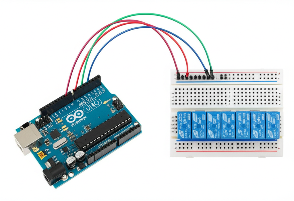
Most relay modules come with built-in driver circuits, optoisolation, and LED indicators, making them beginner-friendly. These modules typically have control pins labeled IN1 to INn, power pins (VCC and GND), and a separate JD-VCC pin for the relay coil power. Connect the IN pins to Arduino digital outputs, VCC to 5V (if using Arduino’s power), and GND to ground.
The JD-VCC jumper determines whether the relay coil is powered from the same source as the logic (Arduino) or an external supply. For systems with more than two relays, remove the jumper and connect an external 5V or 12V power supply to JD-VCC and GND to prevent voltage drops and Arduino resets. This separation ensures stable operation and protects your microcontroller.
Designing a Custom Relay Driver Circuit
If you’re using individual electromechanical relays, you’ll need to build a driver circuit for each. An NPN transistor like the 2N2222 acts as a switch, controlled by the Arduino’s digital pin through a current-limiting resistor (usually 1kΩ). The relay coil connects between the power supply and the transistor’s collector, while the emitter goes to ground.
A flyback diode (1N4007) must be placed across the relay coil to absorb voltage spikes generated when the coil is de-energized—this protects the transistor and Arduino. For driving multiple relays efficiently, consider using integrated circuits like the ULN2003 (7-channel Darlington array) or TPIC6B595 (high-current shift register), which reduce component count and improve reliability.
Power Supply Considerations
Each relay coil draws current—typically 70–100mA at 5V. A 4-channel module may require up to 400mA, which is near the limit of the Arduino Uno’s onboard regulator. When using 8 relays or more, always use an external power supply for the relay coils to avoid overheating or brownouts.
Ensure the external supply matches the relay’s voltage rating and can deliver sufficient current. For example, a 12V 1A supply can comfortably power a 4-relay 12V module. Proper power management is crucial for long-term reliability, especially in unattended automation systems.
Programming the Arduino – Code for Controlling Multiple Relays
Basic Relay Control – Turn Relays On/Off
Controlling relays with Arduino is straightforward using the digitalWrite() function. Below is a simple sketch that turns on four relays one after another with a delay:
// Define relay pins
const int relay1 = 2;
const int relay2 = 3;
const int relay3 = 4;
const int relay4 = 5;


void setup() {
  // Set relay pins as outputs
  pinMode(relay1, OUTPUT);
  pinMode(relay2, OUTPUT);
  pinMode(relay3, OUTPUT);
  pinMode(relay4, OUTPUT);
}

void loop() {
  // Turn on each relay for 2 seconds
  digitalWrite(relay1, HIGH); // Activates relay
  delay(2000);
  digitalWrite(relay2, HIGH);
  delay(2000);
  digitalWrite(relay3, HIGH);
  delay(2000);
  digitalWrite(relay4, HIGH);
  delay(2000);

// Turn all off
  digitalWrite(relay1, LOW);
  digitalWrite(relay2, LOW);
  digitalWrite(relay3, LOW);
  digitalWrite(relay4, LOW);
  delay(5000); // Wait before repeating
}
Advanced Control – Timers, Delays, and Sequencing
Using delay() blocks other operations. For non-blocking timing, use millis(). The following example activates relays in a staggered sequence without stopping the program:
unsigned long previousMillis = 0;
const long interval = 1000; // 1 second
int currentRelay = 2;


void loop() {
  unsigned long currentMillis = millis();
  if (currentMillis - previousMillis >= interval) {
    previousMillis = currentMillis;

if (currentRelay <= 5) {
      digitalWrite(currentRelay, HIGH);
      currentRelay++;
    }
  }
}
Integrating Sensors for Smart Automation
Relays become truly smart when paired with sensors. For example, use a DHT11 temperature sensor to turn on a fan when the room gets too hot:
includedefine DHTPIN 7 define RELAY_FAN 6 dht DHT; void loop() { DHT.read11(DHTPIN); if (DHT.temperature > 28) { digitalWrite(RELAY_FAN, HIGH); } else { digitalWrite(RELAY_FAN, LOW); } delay(2000); }
Remote Control via Serial or Bluetooth
You can control relays via the Serial Monitor by sending text commands:
String command;

void loop() {
  if (Serial.available()) {
    command = Serial.readString();
    if (command.indexOf("RELAY1 ON") >= 0) {
      digitalWrite(2, HIGH);
    } else if (command.indexOf("RELAY1 OFF") >= 0) {
      digitalWrite(2, LOW);
    }
  }
}
Add an HC-05 Bluetooth module to receive commands from a smartphone app, enabling wireless control without additional hardware complexity.
Safety Best Practices When Working with Relays
Working with relays—especially when switching AC mains—requires strict adherence to safety protocols. Always disconnect power before making or modifying connections to high-voltage circuits. Use insulated enclosures to prevent accidental contact with live terminals, and clearly label all wires to avoid confusion during maintenance.
Never exceed the voltage or current rating of the relay contacts—doing so can lead to arcing, fire, or equipment failure. Optoisolated relay modules provide an extra layer of protection by electrically separating the Arduino from high-power circuits, reducing the risk of damage from surges or noise.
For permanent installations, include fuses or circuit breakers on the load side to protect against overcurrent. Also, ensure proper ventilation around relay modules, as continuous operation can generate heat—especially with multiple relays activated simultaneously.
Real-World Applications of Arduino Multi-Relay Systems
Multi-relay Arduino systems have diverse applications across industries and everyday life. In home automation, they can control lighting circuits, garage doors, HVAC systems, or water pumps based on time, sensor input, or user commands. Industrial setups use them for machine sequencing, motor control, and conveyor belt automation, improving efficiency and reducing manual intervention.
In agriculture, Arduino-based relay controllers automate irrigation systems, turning water valves on and off based on soil moisture readings. Greenhouse environments benefit from temperature- and humidity-driven ventilation and heating controls. Energy-conscious users build smart power strips that cut off standby power to devices when not in use.
By integrating Wi-Fi-enabled boards like ESP32, these systems can connect to the cloud, allowing remote monitoring and control via mobile apps or platforms like Blynk, Home Assistant, or Node-RED—turning a simple relay controller into a full-fledged IoT device.
Troubleshooting Common Issues
Even well-designed systems can encounter problems. If a relay fails to activate, first verify the wiring, power supply, and Arduino code. Ensure the control pin is correctly defined and set to output mode. Random or unintended relay triggering is often caused by floating inputs—add pull-down resistors (10kΩ) from the control pin to ground to stabilize the signal.
If the Arduino resets when a relay switches, it’s likely due to a voltage drop from shared power. Use a separate power supply for the relay coil. Overheating relay modules may indicate excessive current draw—check the total load and ensure the power supply can handle it. Lastly, electrical noise can interfere with sensor readings; use shielded cables or ferrite beads to reduce interference.
Conclusion – Building Smarter with Arduino and Relays
Controlling multiple relays with Arduino opens the door to powerful, intelligent automation systems that respond to real-time conditions and user input. With basic electronics knowledge and simple coding, you can build reliable controllers for lights, appliances, motors, and more. The combination of Arduino’s flexibility and the robust switching capability of relays makes it an ideal platform for DIY enthusiasts and professionals alike.
By integrating sensors, timers, and wireless communication, your relay system evolves from simple switching to smart decision-making. Whether you're managing a home environment, automating a farm, or prototyping an industrial solution, the skills you gain here are directly transferable. Start small, experiment often, and gradually expand your setup—perhaps by adding Wi-Fi control, a web interface, or integration with smart home ecosystems. The future of automation is in your hands.
Frequently Asked Questions (FAQ)
Can I control 8 relays with an Arduino Uno?
Yes, Arduino Uno has 14 digital I/O pins, so you can directly control an 8-channel relay module. Just ensure the power supply can handle the total current draw of all relays.
Do I need external power for the relay module?
If you're using all relays simultaneously, it's recommended to power the relay coil (JD-VCC) externally to avoid overloading the Arduino’s 5V regulator.
How do I prevent relay clicking noise in my project?
Use solid-state relays (SSRs) instead of electromechanical ones, or place the relay module in an enclosed box to dampen sound. Adding capacitors across the coil can also help.
Can I control relays over the internet using Arduino?
Yes, by using an ESP8266 or ESP32 instead of a standard Arduino, or by connecting an Ethernet/Wi-Fi shield to your Arduino, you can enable internet-based relay control via web servers or IoT platforms like Blynk or Home Assistant.
Is it safe to switch AC loads with Arduino relays?
Yes, but only if the relay is rated for the AC voltage and current (e.g., 120V/240V AC). Always follow electrical safety guidelines, use proper enclosures, and avoid touching live circuits.