
Table of Contents Show
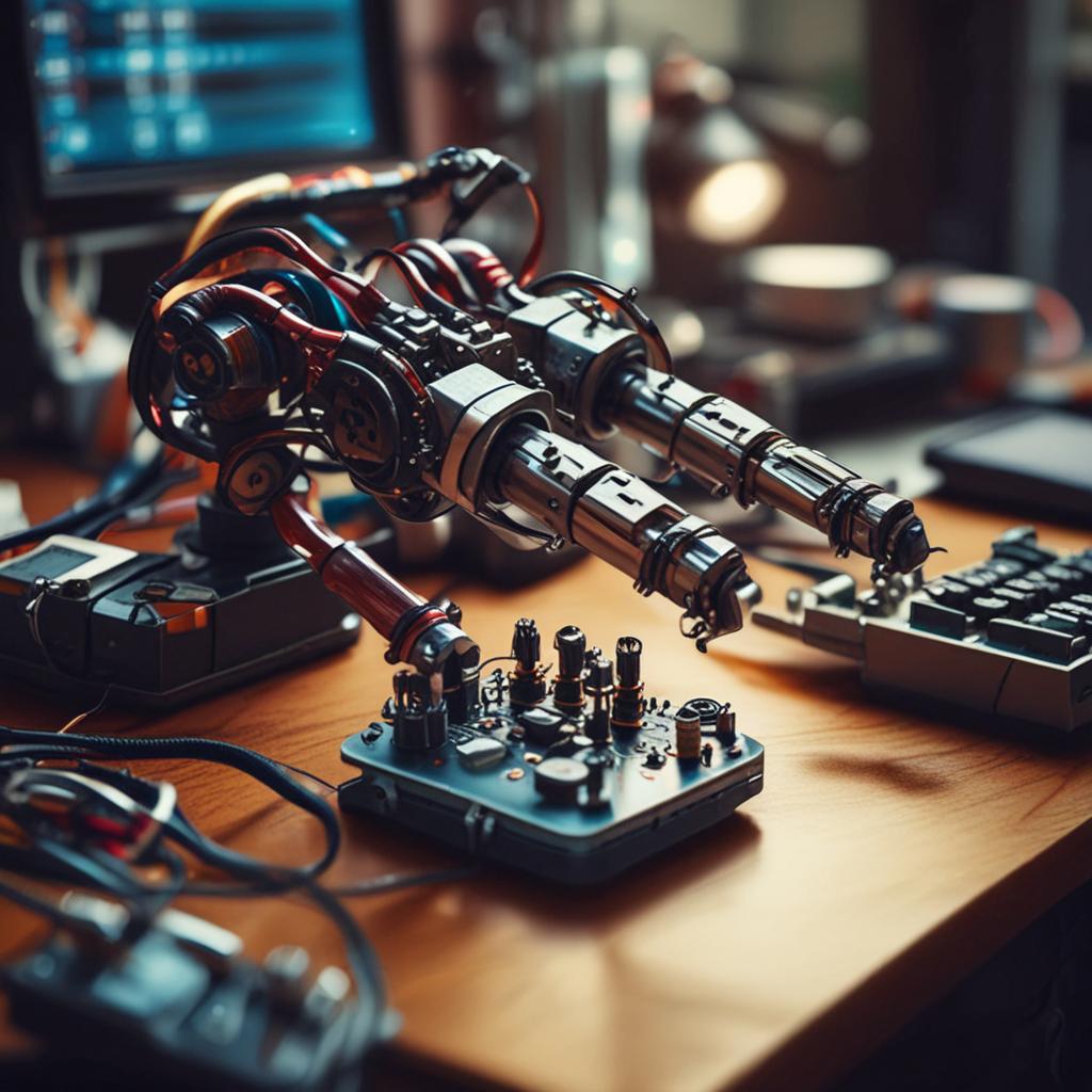
The world of robotics is no longer confined to high-tech labs and industrial floors—it’s now accessible to hobbyists, students, and makers everywhere. With affordable components and open-source platforms, building functional robotic systems has become an exciting and educational DIY adventure. One of the most engaging projects you can tackle is controlling a robotic arm using an Arduino and a joystick. This setup not only teaches the fundamentals of electronics, programming, and mechanics but also lays the groundwork for more advanced automation applications. In this guide, you’ll learn how to bring a robotic arm to life through intuitive joystick control, covering everything from wiring and coding to calibration and troubleshooting. Whether you’re a beginner or looking to expand your skills, this step-by-step tutorial will help you build a responsive, functional robotic arm with ease.
To successfully control a robotic arm with an Arduino and joystick, you’ll need a few essential components. Selecting the right parts ensures smooth operation and minimizes compatibility issues. Below is a detailed list of hardware and software required for the project.

Arduino Board (Uno or Similar)
The Arduino is the brain of this project, known for its simplicity, strong community support, and extensive documentation. The Arduino Uno is highly recommended due to its reliability and availability of PWM pins for servo control. Alternatives like the Arduino Nano or Mega can also be used depending on the number of servos you plan to operate.
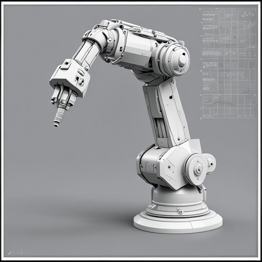
Robotic Arm Kit or DIY Servo Setup
You can choose between a pre-assembled robotic arm kit or build your own using 3D-printed parts and servo motors. Kits with 4 to 6 degrees of freedom (DOF) are ideal for this project, offering a good balance between complexity and functionality. Each joint of the arm will be driven by a servo motor, enabling precise angular control.
Joystick Module (Analog 2-Axis)
A standard analog joystick module, such as the KY-023 or PS2-style joystick, provides two-axis control (X and Y) through analog voltage outputs. These modules typically include a push-button for additional functions like gripper activation. The joystick’s intuitive interface makes it perfect for real-time robotic arm control.
Servo Motors (MG996R, SG90, etc.)
Servo motors are the actuators responsible for moving each joint of the robotic arm. For lightweight arms, SG90 micro servos work well. For heavier loads or sturdier builds, high-torque servos like the MG996R are better suited. The number of servos needed depends on the arm’s DOF—typically 4 to 6 servos for a fully functional arm.
Jumper Wires, Breadboard, and Power Supply
You’ll need male-to-female and male-to-male jumper wires to connect components. A breadboard helps organize wiring during prototyping. Crucially, use an external power supply (5V–6V) such as a battery pack or DC adapter to power the servos, as the Arduino alone cannot supply enough current for multiple motors without risking damage.
Software: Arduino IDE
The Arduino Integrated Development Environment (IDE) is free and available for all major operating systems. Make sure to install the latest version to ensure compatibility. The built-in Servo.h library will be used to control the servos, so no additional library installation is required unless you plan to add advanced features.
How the System Works: Principle of Operation
The robotic arm control system operates on a simple yet effective signal chain. When you move the joystick, it outputs analog voltage values corresponding to the X and Y axis positions. The Arduino reads these values through its analog input pins, converts them into usable data, and then sends proportional PWM signals to the servo motors. Each servo rotates to a specific angle based on the mapped joystick input, resulting in coordinated arm movement.
The analog readings from the joystick range from 0 to 1023, representing the full deflection of the stick. These values are mapped to a servo-friendly range of 0 to 180 degrees using the Arduino’s map() function. This translation allows smooth, proportional control of the robotic joints. Maintaining a common ground between the Arduino and the external power supply is essential for accurate signal reference and stable operation.
Step-by-Step Assembly Guide
With all components ready, it’s time to assemble the system both mechanically and electrically. Follow these steps carefully to ensure a reliable and functional setup.
Assembling the Robotic Arm
If using a kit, follow the manufacturer’s instructions to assemble the arm segments and mount the servos at each joint. Ensure all screws are tight and gears are properly aligned to prevent binding. For custom builds, 3D-print the parts and verify that each joint moves smoothly before securing the servos. Test range of motion manually to avoid mechanical interference during operation.
Wiring the Components
Connect the joystick module to the Arduino as follows:
- Joystick VCC → Arduino 5V
- Joystick GND → Arduino GND
- Joystick VRx → Arduino A0
- Joystick VRy → Arduino A1
For each servo motor:
- Servo signal wire (usually yellow or white) → Arduino PWM pin (e.g., D3, D5, D6, D9)
- Servo power wire (red) → External 5V–6V power supply positive rail
- Servo ground wire (brown or black) → External power supply negative rail AND Arduino GND (common ground)
Use a breadboard or terminal block to distribute power and ground connections neatly.
Essential Checklist
Goal Definition
Clearly define objectives and success metrics
Resource Planning
Allocate necessary time, budget, and personnel
Implementation Strategy
Develop step-by-step execution plan
Quality Assurance
Establish testing and validation procedures
Performance Monitoring
Set up tracking and reporting systems
Essential items for How to Control a Robotic Arm with Arduino and Joystick
Power Management Tips
Never power more than one or two small servos directly from the Arduino’s 5V pin. Doing so can overload the onboard voltage regulator and cause resets or damage. Always use an external power source rated for the total current draw of your servos (e.g., 4xAA batteries or a 5V/2A DC supply). Adding a 100µF capacitor across the power rails near the servos helps suppress voltage spikes and reduces motor jitter.
Writing the Arduino Code
The software component translates user input into physical motion. The code is written in the Arduino IDE and uses the built-in Servo library to manage motor control with precision.
Setting Up the Arduino IDE
Open the Arduino IDE and ensure the correct board and port are selected under the Tools menu. The Servo.h library is included by default, so you can include it at the top of your sketch using #include <Servo.h>. No additional installations are needed for basic functionality.
Code Breakdown: Initialization and Variables
Begin by creating Servo objects for each joint and assigning them to specific digital pins. Define analog input pins for the joystick axes. Variables will store raw analog readings and mapped servo angles. For a 4-DOF arm, you might control the base, shoulder, elbow, and gripper—each linked to one servo.
Mapping Joystick Input to Servo Movement
In the main loop, use analogRead() to get values from A0 (X-axis) and A1 (Y-axis). These values are then mapped from 0–1023 to 0–180 degrees using the map() function. To prevent erratic movement, apply constrain() to limit angles within the servo’s mechanical range and consider averaging multiple readings for smoother response.
Complete Sample Code with Comments
Here’s a simplified example for a 4-DOF arm:
include <Servo.h>
Servo baseServo, shoulderServo, elbowServo, gripperServo;
const int joyX = A0; const int joyY = A1; const int buttonPin = 2;
void setup() { baseServo.attach(9); shoulderServo.attach(10); elbowServo.attach(11); gripperServo.attach(12); pinMode(buttonPin, INPUT_PULLUP); }
void loop() { int xVal = analogRead(joyX); int yVal = analogRead(joyY); int baseAngle = map(xVal, 0, 1023, 0, 180); int shoulderAngle = map(yVal, 0, 1023, 0, 180); int elbowAngle = map(yVal, 0, 1023, 180, 0); // Inverted
baseServo.write(baseAngle); shoulderServo.write(shoulderAngle); elbowServo.write(elbowAngle);
// Gripper control via button if (digitalRead(buttonPin) == LOW) { gripperServo.write(20); // Closed } else { gripperServo.write(90); // Open }
delay(15); // Small delay for stability
}
Adjust pin assignments and angle ranges based on your arm’s configuration. Calibrate neutral positions by checking servo behavior when the joystick is centered.
Testing and Calibration
Once the hardware and software are in place, thorough testing ensures safe and accurate operation. Take time to fine-tune the system before full use.
Initial Power-Up and Servo Check
Power the system and observe each servo. When the joystick is at rest, servos should hold a neutral position without jittering. If a servo moves unexpectedly, check wiring and verify that the signal pin is correctly assigned in code. Use the Serial Monitor to print analog values and confirm joystick responsiveness.
Fine-Tuning Movement Range
Adjust the minimum and maximum angles in the map() function to match the physical limits of each joint. Over-rotation can strip servo gears, so limit angles conservatively. For example, if a shoulder servo only moves 150 degrees safely, map the input to 15–165 instead of 0–180.
Joystick Sensitivity and Dead Zone Adjustment
Implement a dead zone around the center (e.g., 450–570) to prevent unintended movement from joystick drift. If the arm feels too sensitive, scale the output range or add smoothing using a moving average filter. This improves control precision and user experience.
Troubleshooting Common Issues
Even with careful setup, issues may arise. Here are solutions to common problems encountered during the project.
Servos Twitching or Jerking
This is often caused by insufficient or unstable power. Ensure servos are powered externally and share a common ground with the Arduino. Loose connections or long wires can also introduce noise—check all joints and consider adding a decoupling capacitor (100µF) near the servo power lines.
Joystick Not Responding or Inconsistent
Use the Serial Monitor to print raw analog values from A0 and A1. If readings are erratic or stuck, inspect wiring and ensure the joystick module is receiving stable 5V. Recalibrate center values if the neutral point deviates significantly from 512.
Delayed or Laggy Movement
Avoid using delay() functions in long loops, as they block other operations. Replace with non-blocking timing using millis() for better responsiveness. Reduce or disable serial printing during active control to prevent communication lag.
Mechanical Binding in the Arm
If joints feel stiff or resist movement, check for over-tightened screws or misaligned parts. Disassemble and reassemble if necessary. Lightly lubricate gears with silicone grease if friction is an issue, but avoid oil-based lubricants that could damage plastic components.
Advanced Enhancements and Project Ideas
Once the basic control system is working, you can expand functionality for more sophisticated applications.
Adding Gripper Control with a Button
Use the joystick’s built-in push-button or add a separate switch to toggle the gripper between open and closed states. Modify the code to detect button presses and adjust the gripper servo angle accordingly for object pickup and release.
Implementing Inverse Kinematics (IK)
Instead of controlling each joint independently, IK allows you to move the arm’s end-effector (gripper) in 3D space, and the software calculates the required joint angles. Libraries like RobotArm3D or IKSolver can help implement this for smoother, more natural motion.
Wireless Control with Bluetooth (HC-05 Module)
Integrate an HC-05 Bluetooth module to enable wireless control via a smartphone app. Pair the module with your phone and use a serial-based app to send commands, turning your mobile device into a remote controller.
Recording and Playback Movements
Use an SD card module or the Arduino’s EEPROM to record servo positions over time. Then, create a playback function to automatically repeat tasks—ideal for automation or demonstration purposes.
Conclusion
Controlling a robotic arm with an Arduino and joystick is a rewarding project that blends electronics, coding, and mechanics into a tangible, functional system. By following this guide, you’ve learned how to assemble the hardware, wire the components safely, write responsive code, and troubleshoot common issues. This project not only teaches core engineering concepts but also serves as a foundation for more advanced automation and robotics experiments.
We encourage you to customize your robotic arm—change the design, add sensors, or integrate voice or vision control. Share your builds online, contribute to maker communities, and keep pushing the boundaries of what’s possible. The skills you gain here open doors to fields like industrial automation, assistive robotics, and even AI-driven systems. Now that you’ve mastered the basics, the next move is yours.
Frequently Asked Questions (FAQ)
Can I use a different microcontroller instead of Arduino?
Yes, platforms like ESP32 or Raspberry Pi can control servos and read joystick inputs. However, they may require different voltage levels, libraries, or programming environments. The ESP32 works well with the Arduino IDE and offers more GPIOs, while Raspberry Pi requires PWM setup via software or add-on boards.
How many servos can an Arduino control at once?
The Arduino Uno can control up to 12 servos using the standard Servo library. However, the real limitation is power delivery. Always use an external power supply when driving more than two servos to avoid damaging the board.
Why is my robotic arm shaky or vibrating?
Shaking is usually due to inadequate power supply or lack of a common ground between the Arduino and servos. Use a dedicated battery pack for the servos and ensure all grounds are connected. Adding capacitors across the power lines can also stabilize voltage.
Can I control multiple joints with one joystick?
Yes, but typically one joystick axis controls one servo. For multi-axis movement, you can switch control modes (e.g., press a button to toggle between shoulder and elbow) or use a second joystick for more simultaneous control.
Is coding knowledge required for this project?
Basic familiarity with Arduino programming is helpful, but not mandatory. The sample code provided is beginner-friendly, well-commented, and easy to modify. With step-by-step guidance, even those new to coding can successfully complete this project.


