Table of Contents Show
Controlling the speed of a DC motor lies at the heart of countless electronic and automation systems, from simple hobbyist robots to complex industrial machinery. The ability to adjust how fast a motor spins opens up possibilities for precision, efficiency, and dynamic control. With the rise of accessible microcontrollers like Arduino, what once required complex circuitry can now be achieved with a few wires, some code, and a clever technique known as Pulse Width Modulation (PWM). In this guide, we’ll walk you through building a reliable DC motor speed control system using Arduino and PWM—ideal for beginners and makers looking to deepen their understanding of motor control.
What Is a DC Motor?
A DC motor converts direct current electrical energy into mechanical rotation using the principles of electromagnetic induction. When current flows through a coil inside a magnetic field, it generates a force that causes the motor’s shaft to rotate. The most common type used in DIY electronics is the brushed DC motor, known for its simplicity, low cost, and ease of control. These motors are typically rated by voltage (e.g., 6V, 12V), current draw, revolutions per minute (RPM), and torque, which determines their ability to perform physical work.
Why Control Motor Speed?
Fixed-speed motors are limited in functionality. In contrast, variable speed control enables adaptive performance—think of a drone adjusting propeller speed for stable flight or a conveyor belt slowing down to handle delicate items. Controlling motor speed improves energy efficiency, reduces mechanical stress, and allows for precise movements in robotics and automation. Without speed regulation, systems are either too aggressive or too sluggish for real-world tasks.
Methods of DC Motor Speed Control
There are several ways to control a DC motor’s speed. The most straightforward is varying the input voltage, but this is inefficient and can lead to poor motor performance at low voltages. Another method uses H-bridge circuits to reverse polarity and control direction. However, the most effective and widely used technique in microcontroller-based projects is Pulse Width Modulation (PWM). PWM delivers full voltage in rapid pulses, adjusting the “on” time to control average power—offering high efficiency, minimal heat loss, and seamless integration with digital systems like Arduino.
Introduction to PWM (Pulse Width Modulation)
What Is PWM?
Pulse Width Modulation (PWM) is a digital method of simulating variable voltage by rapidly switching a signal between on (high) and off (low) states. The key concept is the duty cycle—the percentage of time the signal is on during one cycle. For example, a 25% duty cycle means the signal is on for a quarter of the time, delivering roughly a quarter of the full power. This is similar to how a blinking LED appears dimmer at lower frequencies—the human eye perceives average brightness, just as a motor perceives average voltage.
How PWM Controls DC Motor Speed
When PWM is applied to a DC motor, the average voltage determines the rotational speed. A higher duty cycle means more power and higher RPM, while a lower duty cycle slows the motor down. The PWM frequency must be high enough (typically above 20 kHz) to prevent audible buzzing or jerky motion. At optimal frequencies, the motor runs smoothly because the mechanical inertia smooths out the rapid pulses, effectively acting like a steady voltage input.
PWM Capabilities of Arduino
Most Arduino boards, including the popular Uno and Nano, feature several PWM-capable digital pins marked with a ~ symbol (e.g., pins 3, 5, 6, 9, 10, 11 on Arduino Uno). These pins generate PWM signals using internal timers, with a default frequency of approximately 490 Hz (or 980 Hz on some pins). The analogWrite(pin, value) function is used to set the duty cycle, where the value ranges from 0 (0%, always off) to 255 (100%, always on). While simple and effective, this method uses fixed-frequency PWM unless modified via timer registers.
Components Required for the Project
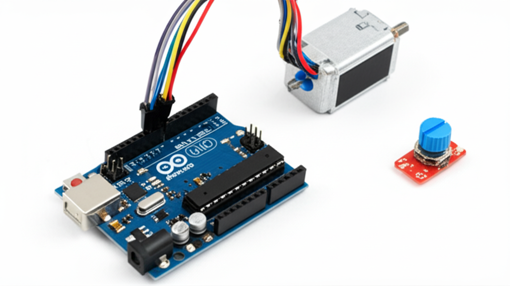
Essential Hardware List
- Arduino Uno or Nano
- DC motor (6V–12V, moderate current draw)
- External power supply (battery pack or adapter matching motor voltage)
- L298N or L293D motor driver module
- 10kΩ potentiometer
- Breadboard and jumper wires
- Flyback diode (1N4007, if not built into driver)
- Capacitor (optional, 100µF across motor terminals for noise suppression)
Role of Each Component
The potentiometer acts as a manual input device—turning it changes resistance, which the Arduino reads as an analog voltage to determine motor speed. The motor driver is crucial because the Arduino cannot supply enough current to drive most motors directly. The L298N or L293D module handles high-current loads and isolates the motor’s power from the microcontroller. A flyback diode protects the circuit from voltage spikes (back EMF) generated when the motor stops or changes speed, preventing damage to sensitive components.
Circuit Design and Connections
Circuit Diagram Overview
The system flows as follows: the potentiometer connects to an Arduino analog input to set speed. The Arduino processes this value and sends a PWM signal to the motor driver’s enable pin. The driver powers the motor using an external supply while receiving direction signals (if applicable) from digital pins. All grounds—Arduino, motor driver, and power supply—are connected together to ensure a common reference.

Step-by-Step Wiring Instructions
- Connect the potentiometer: left pin to 5V, right pin to GND, middle pin to analog pin A0 on Arduino.
- Connect the L298N motor driver: IN1 to Arduino pin 8, IN2 to pin 7, ENA to pin 9 (PWM capable).
- Attach the DC motor to the motor A output terminals (OUT1 and OUT2) on the L298N.
- Connect the external power supply’s positive to the L298N’s 12V input and negative to GND.
- Join the Arduino GND and L298N GND pins to complete the common ground.
Safety and Best Practices
Always power the motor from an external source—not the Arduino’s 5V pin—to avoid overloading and potential damage. Double-check wiring, especially polarity, before powering up. If your motor driver doesn’t have built-in flyback diodes, solder 1N4007 diodes across the motor terminals. For noisy environments, add a 100µF capacitor in parallel with the motor to suppress electrical noise.
Arduino Code for PWM Speed Control
Code Explanation
The following Arduino sketch reads the potentiometer value, maps it to a PWM range, and adjusts motor speed accordingly. It also sets a default direction by keeping one input high and the other low.

// Speed control of DC motor using PWM
const int potPin = A0;     // Potentiometer connected to A0
const int enA = 9;         // PWM pin to enable motor
const int in1 = 8;         // Control pin 1
const int in2 = 7;         // Control pin 2
void setup() { pinMode(enA, OUTPUT); pinMode(in1, OUTPUT); pinMode(in2, OUTPUT); Serial.begin(9600); // For debugging }
void loop() { int potValue = analogRead(potPin); // Read 0-1023 int pwmValue = map(potValue, 0, 1023, 0, 255); // Scale to 0-255
digitalWrite(in1, HIGH); // Set direction (forward) digitalWrite(in2, LOW);
analogWrite(enA, pwmValue); // Apply PWM signal
Serial.print(“Pot: “); Serial.print(potValue); Serial.print(” | PWM: “); Serial.println(pwmValue);
delay(10); // Small delay for stability
}
Uploading and Testing the Code
Upload the code using the Arduino IDE. Open the Serial Monitor to observe real-time values from the potentiometer and PWM output. If the motor doesn’t respond, verify wiring and ensure the enable (ENA) pin is connected to a PWM-capable pin. If the motor runs erratically, check for loose connections or unstable power. Use the Serial output to confirm that the analog read values change when turning the potentiometer.
Advanced Variations and Enhancements
Adding Direction Control (Forward/Reverse)
To enable bidirectional control, modify the code to toggle IN1 and IN2. For example, setting IN1 HIGH and IN2 LOW makes the motor go forward; reversing the logic makes it go backward. You can use a second potentiometer, push buttons, or a switch to change direction dynamically.
Speed Control via Serial Input
Enhance the project by allowing speed input through the Serial Monitor. Use Serial.parseInt() to read an integer between 0 and 255, then apply it directly to analogWrite(). This enables precise speed setting without physical knobs.
Using Push Buttons or IR Remote
Replace the potentiometer with two buttons—one to increase speed and another to decrease it. Alternatively, integrate an IR receiver and remote control for wireless operation. Libraries like IRremote.h make decoding remote signals straightforward.
Feedback-Based Control (Optional)
For closed-loop speed regulation, attach a rotary encoder to the motor shaft. Measure actual RPM and compare it to the desired speed. Implement a PID (Proportional-Integral-Derivative) algorithm to adjust PWM automatically and maintain consistent speed under load—an advanced but powerful technique used in real-world applications.
Troubleshooting Common Issues
Motor Not Spinning
Check that the external power supply is connected and functional. Ensure the motor driver’s enable pin is linked to a PWM pin and receiving a signal. Verify that IN1 and IN2 have correct logic levels. Use a multimeter to confirm voltage at the motor terminals.
Motor Jerks or Vibrates
This is often due to low PWM frequency. While Arduino’s default 490 Hz works for many motors, some may require higher frequencies. Consider using a different timer or a dedicated PWM library. Also, check for loose connections or insufficient power.
Arduino Resets or Overheats
This typically results from back EMF or ground loops. Ensure the motor and Arduino share a common ground and that a flyback diode is in place. Avoid powering the Arduino through the motor driver unless explicitly designed for it.
Speed Not Responding to Potentiometer
Open the Serial Monitor to verify that analog readings change when turning the knob. If values are stuck, check the potentiometer wiring—especially the middle pin connection to A0. Ensure the outer pins are connected to 5V and GND.
Applications of PWM Motor Control
PWM-based motor control is widely used in robotics for differential drive systems, allowing precise turning and speed adjustments. In home automation, it powers smart fans, automated blinds, and aquarium pumps. Industrial applications include conveyor belts, sorting machines, and CNC systems. It’s also a staple in STEM education, helping students grasp core concepts in electronics, programming, and control theory through hands-on learning.
Conclusion
Speed control of a DC motor using Arduino and PWM is a foundational skill for any electronics enthusiast or engineer. By combining simple hardware—Arduino, motor driver, and potentiometer—with intuitive code, you can build a responsive and efficient speed control system. This setup not only works reliably but also serves as a springboard for more advanced projects involving direction control, remote operation, and feedback-based regulation. We encourage you to build this circuit, experiment with enhancements, and share your innovations with the maker community.
Frequently Asked Questions (FAQ)
Can I control a high-power DC motor directly with Arduino?
No. Arduino digital pins can only supply limited current (typically 20–40 mA), which is insufficient for most DC motors. Always use a motor driver or power transistor to handle higher loads and protect the microcontroller.
Why is my motor making a buzzing sound?
A buzzing or humming noise is usually caused by low PWM frequency. Arduino’s default 490 Hz may fall within the audible range. Try using a motor driver with built-in high-frequency PWM or adjust timer settings in code to increase frequency beyond 20 kHz.
Can I use any Arduino board for this project?
Yes, most Arduino-compatible boards—including Uno, Nano, Mega, and even ESP32-based boards—can be used as long as they have PWM-capable pins and sufficient I/O. Just ensure the code and pin mappings are adjusted accordingly.
Do I always need a motor driver?
For small vibration motors or very low-current applications, a transistor like the 2N2222 may suffice. However, for reliability, safety, and added features like direction control, a dedicated motor driver like the L298N is strongly recommended.
How precise is PWM speed control?
In open-loop systems (without feedback), PWM offers reasonable precision under consistent load. However, speed can vary with battery voltage or mechanical resistance. For high accuracy, add an encoder and implement closed-loop PID control to maintain constant RPM regardless of conditions.


